Mobile Usability Testing Rig for m.cdlib
By Jane Lee, CDL Senior Assessment Analyst
In the summer of 2010, CDL’s User Experience Design team began investigating the possibility of creating a mobile version of CDL’s newly redesigned website. As part of its design process for creating an interface optimized for mobile devices, the team set out to test its prototype mobile website, m.cdlib, with users. This article describes the process of creating the tool used for mobile usability testing and includes the following topics:
- Challenges of Mobile Usability
- Research
- Designing and Building the Prototype
- Modifying the Rig
- A Few Lessons Learned
- Resources
This article will not delve into the details of usability testing or the results of the tests.
Challenges of Mobile Usability
The California Digital Library (CDL) has had a formal usability practice in place since 2004, and we have carried out usability tests on our websites and web services using laptop or desktop computers. For usability testing of our mobile site, we briefly considered using an emulator with our existing set-up. However, as CDL’s senior usability analyst and DIY enthusiast, I rejected that idea knowing there had to be a way to test on a more authentic platform. After all, interacting with an emulator on a full size screen using non-mobile input devices — i.e., full size keyboard and mouse — is not the same as holding a device in one’s hand and using it.
Another consideration was how to best capture users’ behaviors and interactions, so we could share them with our team. For standard usability testing, we used screen recording software and a backup digital audio recorder. Our team had recently acquired a digital camcorder, but using it wouldn’t give us a detailed view of the screen of the mobile device or users’ interactions with it. This camcorder set-up would also force the user to remain relatively still. Instead, I decided to build something handheld that would hold a small camera in place over the mobile device.
Research
I began with a Google search for existing set-ups using phrases, such as “mobile device usability.” After browsing through a few pages of results, I discovered this post. The author had included two images of the rig he had built, and its simplicity made me confident that I could create our own rig based on his design. I just had to mind two constraints: money and time.
The bowmast.com design used an analog CCTV camera, but we did not have the budget or the time to acquire that kind of equipment. I decided to see if I could use CDL’s webcam, which staff normally used to hold video-conferences. Then, I went to the website of my neighborhood TAP Plastics store to research the cost of creating the plastic part of the rig that would hold the camera and the mobile device in place.
After browsing TAP’s selection of plastics, I estimated that it would cost about $30 in materials to make the rig’s frame. I went to my supervisor to get approval before heading to TAP to see if they could manufacture the rig within three days. (We were scheduled to hold our first usability test the next week.) The manager at TAP Plastics said that all they needed were the exact measurements for the rig, so my next step was to finalize my design.
Designing and Building the Prototype
The bowmast.com design was a great starting point. I briefly considered putting together a flat platform with an attached gooseneck for the camera, which would have provided the greatest flexibility in positioning the camera. However, I had great difficulty finding a suitable gooseneck at my local hardware store, and I decided that the resulting Frankenstein rig might distract users.
I proceeded to design my version of rig based on the following photo:
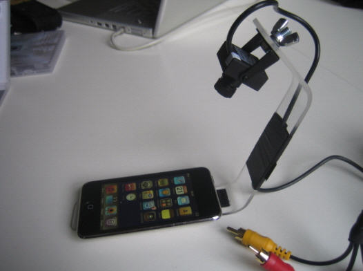
I had to figure out the dimensions and angles that would allow the rig to work with CDL’s webcam, a Logitech C905. Then, I needed to communicate those measurements to TAP Plastics. After contemplating how long it would take for me to sketch a diagram by hand or learn the basics of Google SketchUp, I decided that a three-dimensional, cardboard prototype would be the most efficient and accurate way to convey my design to TAP.
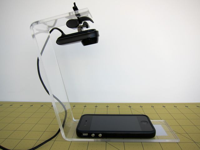
The rig in the photo looked a little skinny to me, so I decided to make the width of the rig just smaller than the width of an iPhone 4. (I knew that our users could be using other mobile devices, but I went with the device that I had on hand.) I cut a strip of cardboard from an Amazon.com box with a box cutter and metal ruler and started playing around with lengths and angles. I didn’t have the webcam with me when I was experimenting, so I did my best to imagine how the webcam would attach using my memory and the following profile image of the webcam from Logitech’s product page:

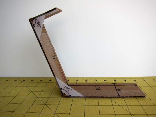
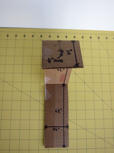
After finding a satisfactory configuration, I cut the cardboard to length and used tape to fix the angles in place. I used my iPhone and an app called Clinometer to measure the angles and a ruler to measure the lengths. With a Sharpie marker, I wrote the measurements directly on the cardboard and tape, as shown below:
I dropped off the cardboard prototype at TAP, where they suggested using 3/16” thick acrylic.
Modifying the Rig
Two days later, I picked up the manufactured rig and the prototype. TAP did a great job, and I rushed back to try it out with the webcam. My original thought was to attach the webcam to the rig using its integrated clip.
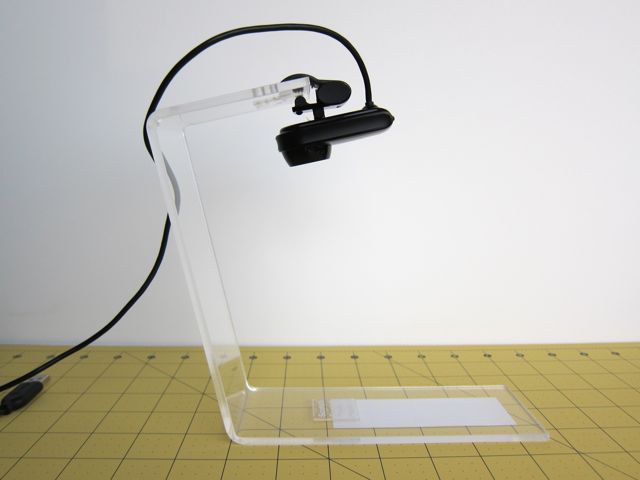
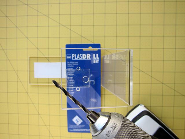
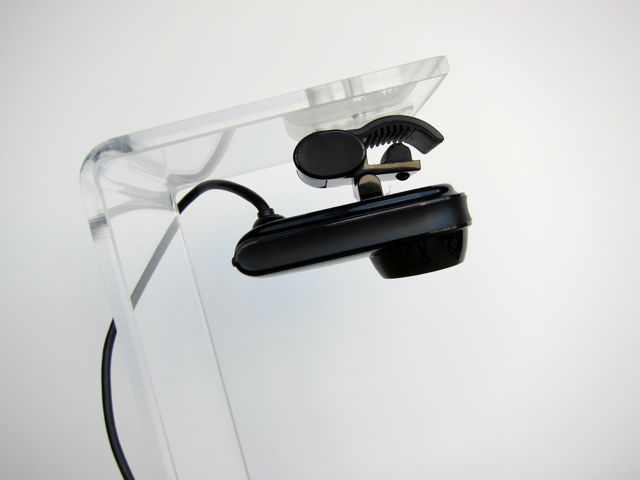
Well, doing that resulted in a recorded image that was upside down. (D’oh!) To fix this, I stuck the webcam to the underside of the overhang with Scotch mounting adhesive. This worked okay, but I worried that the webcam would detach due to gravity eventually. I decided to supplement the adhesive with a zip tie, which required me to drill two holes in the overhang. (I had asked TAP to drill one big hole in the middle to accommodate a bolted camera like the one used in the bowmast.com implementation.)
The result actually looked better, because the webcam didn’t jut out over the platform as much.
To complete the rig, I had to figure out how to attach users’ devices to the rig. I didn’t want to use adhesive Velcro, because it would be difficult to remove and it felt like an imposition on the user. (I personally would not want someone sticking something on my gadgets.) The method I used had to be effective at holding the device in place, non-marking, and removable. I originally wanted to use 3M Command adhesive strips, but the local drugstore had Scotch mounting tape, which seemed like a satisfactory alternative.
A Few Lessons Learned
During the course of our mobile usability testing sessions, we learned the following from the different environments we encountered:
- Certain lighting situations required adjustments to prevent glare on the mobile device’s screen.
- Differing levels of ambient light required changing the exposure level of the camera at each location.
- Meeting users in their workplaces meant that sometimes there were interruptions.
Overall, the video capture of users’ interactions using the rig and Logitech’s software worked very well. We were pleased by the following discoveries:
- The rig held the camera perfectly steady in relation to the device being used, so we could see exactly what actions participants took.
- The Logitech webcam’s software allowed us to disable autofocus and fix the focus of the camera, which is absolutely essential for testing. (Otherwise, the camera’s autofocus would focus on the user’s hand instead of the screen.)
- The software also allowed us to adjust the exposure levels of the camera, which was important because of the different levels of ambient light we encountered in different locations.
- The webcam’s microphone was positioned perfectly to capture the participant’s voice. (This was an unexpected benefit of using the rig.)
Participants’ feedback about their experience using the rig itself was generally very positive. They reported that the webcam’s placement did not obstruct their view of the screen. And after a few minutes, most participants seemed to interact with the rig as though they were holding just their mobile devices. That is, they didn’t seem to notice the rig at all.
Designing and building the rig was one of the most satisfying parts of this round of mobile usability testing. The most frustrating part was converting the captured video files from WMV to MP4 format. (The only video editing software I had was iMovie, which uses MP4. Unfortunately, Logitech’s software recorded in WMV.) After several unsuccessful conversion attempts, I found an application called Wondershare Video Converter that I could use for free, as long as I didn’t mind having a giant watermark on the video. Since I would be screening the video for the User Experience Design team only, I did not bother to eliminate the watermark by buying the full version of Wondershare.
With the success of this first rig, I hope to have the opportunity to refine both the rig itself and our process for mobile usability testing in future usability projects.
Resources
Websites:
Bowmast User Experience Design & Research
TAP Plastics
Hardware:
Logitech C905 Webcam
Windows laptop to run Logitech software
Software:
Logitech software to set up webcam (exposure, focus, etc.) and record video
Wondershare Video Converter (http://www.wondershare.com/video-dvd-software-mac.html) to convert video files
iMovie to obtain highlight clips to share with team
Clinometer to measure angles